The microwave power module (MPM) concept was initiated by the US military. The Tri-Service (Army, Navy, Air Force) officially launched the MPM program in 1991 – with the Naval Research Laboratory as the primary program office. Most TWT companies were given development contracts at that time. The objective? To give a boost to the microwave tube development effort in the US. And to combine the best uses of both vacuum electronics and solid state technologies.
What’s an MPM?
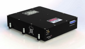
The MPM is a very compact microwave power amplifier. One of the goals of the MPM program was to design standardized modules for multiple applications. Additionally, the frequency bands were supposed to be very generic (i.e., 2 to 6 GHz, 6 to 18 GHz, 18 to 26 GHz, 26 to 40 GHz). For narrowband radar and communication applications, another set of designs were contemplated.
How MPMs Were Developed
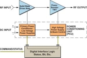
One of the MPM’s signature features is the use of complementary technologies. To achieve wide bandwidth over multi-octave frequency band, the design choice is a helix traveling wave tube (TWT). Operation of the TWT requires high voltage levels, so a high-voltage power supply (HVPS) is an essential necessity for an amplifier using a TWT. However, the TWT and the HVPS are large devices. Most MPM development efforts focused on downsizing the TWT and the HVPS. A mini-booster TWT was selected as the amplifying device due to lower operating voltage levels.
Gain of a helix TWT depends on the length of the helix section consisting of the RF input section, sever and an output section. The input section is the largest, and provides most of the signal amplification. The sever provides isolation from between the input and output. The output section provides the power amplification with relatively low gain.
To reduce the size of the TWT, the obvious choice was to reduce the length of the input section on the helix circuit. Likewise, the reduction in RF gain due to this length reduction is compensated by using a small solid state driver amplifier. The result was a small size RF signal path consisting of a solid state amplifier (SSA) and a short mini-booster TWT (a.k.a. vacuum power booster or micro TWT). Operating cathode voltage of this TWT is in the range of 3Kv to 10Kv – depending on the frequency and RF output power levels. A densely packaged power supply is used to derive the cathode, grid, collectors and heater voltages.
dB Control: 30 Years of MPM Expertise
dB Control has strong roots in MPM technology. In fact, dB Control VP of Business Development Steve Walley was at Varian when they built their first MPMs with a CPI mini booster tube and outsourced power supply back in 1991. And a now-retired dB Control VP (Meppalli Shandas) was one of the leading contributors to the Tri-Service MPM Program in the early 1990s. When the program was initiated nearly three decades ago, dB Control engineers were at the forefront of this technology too.
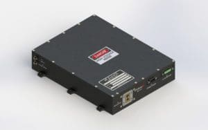
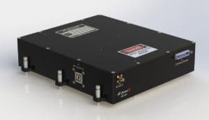
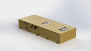
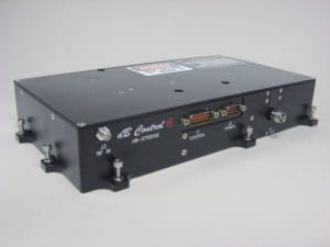
Now in 2022, we have several modern MPM production programs in-house. In fact, the company has delivered hundreds of wideband and narrowband MPMs for radar and ECM applications. Below are some examples of dB Control MPMs for EW, radar and communication applications. Click each caption to download the datasheet: