Building solid state power amplifiers (SSPAs), microwave power modules (MPMs) and traveling wave tube amplifiers (TWTAs) to operate in the Ka-band, Q-band, and other high-frequency bands is more challenging than operating at lower frequencies. Decisions and compromises affecting size, weight, and power, as well as the costs (SWaP-C), become more impactful.
This blog post introduces some of the challenges inherent in working with high frequencies – specifically, Ka-band (continuous wave [CW] and pulsed) and Q-band (CW only). In future posts, we’ll dive into how SWaP-C challenges can be overcome, dispel a few misconceptions about operating in these frequency bands, and address unit designers’ diverse specification needs.
High Frequency Challenges
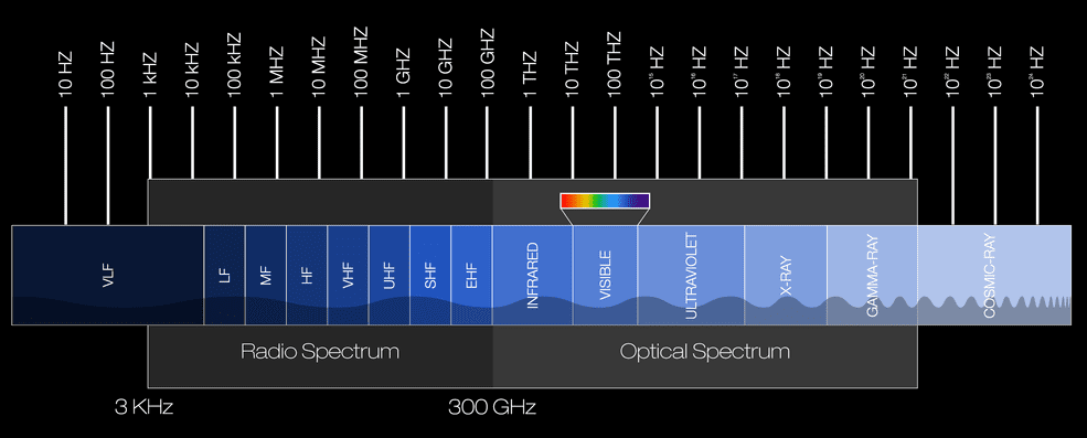
The Ka-band comprises 27 GHz to 40 GHz and includes both a commercial band and a military band. It mainly is used for satellite communications and its focused spot beams allow frequency reuse to boost satellite system capacity.
The Q-band, meanwhile, comprises 36 GHz to 46 GHz and has been applied to satellite communications, radio astronomy studies, and automotive radars. One of the Q-band’s major applications is Advanced Extremely High Frequency (AEHF), a secure, satellite-based military communications band.
In addition to SWaP-C concerns, the design and construction of high-frequency devices in these applications may be affected by use environmental conditions and longer unit lead times.
Size: In part, it becomes more difficult to build products as you progress to higher frequencies because the components (e.g., waveguides and output devices) get much smaller. While SSPAs are starting to find a home in high-frequency applications, TWTs remain the more commonly used output device. However, building a TWT is labor-intensive and requires precise machining, all of which becomes more difficult as the size is reduced.
Weight: This is a balancing game as output devices and components get smaller and lighter as the frequency gets higher. When components shrink to fit in tighter spaces (e.g., manned or unmanned aircraft), their mass typically drops, as well. However, our experience shows that, as the frequency goes up, so do the operating voltages. Therefore, the size and weight of the power supply necessary to drive the output device increases.
Power: Power likely presents the greatest design challenge since, as you go higher in frequency, it’s harder to generate greater power output. Even jumping from the Ka-band to the Q-band is a significant leap, and you can’t match in Q-band the power levels achievable in Ka-band.
Part of the reason for this is atmospheric obscurants. As you operate higher in frequency, adverse environmental conditions, such as rain fade, increase — meaning the environment causes an increasing amount of attenuation. So, if you transmit 100 W through the environment, you may only achieve a fraction of that because the signal is being attenuated through the atmosphere. Thus, operators not only need sufficient power to establish a link, they need enough power to persevere through atmospheric interference (or they risk losing communications and critical data or video transmissions).
Additionally, at higher frequencies, it is more difficult to maintain a unit’s power level at the point of linearity, wherein one watt of input power leads to one watt of power output. When running in a linear region, a unit does not experience distortion at the outer frequencies (i.e., damaging your neighbor’s communication with your signal). Linearity — measured in spectral regrowth, intermodulation, or noise power ratio (NPR) — is particularly relevant in commercial operations for this reason.
Many amplifier customers – particularly in satcom applications – use the terms P1dB and linearity interchangeably, despite the terms not meaning the same thing. P1dB, also called the 1 dB compression point, is the output power level at which gain decreases 1 dB from its constant value (i.e., backed off 1 dB from the theoretical linear power level), and is not a good indication of linearity. Once an amplifier reaches its P1dB it goes into compression and becomes a non-linear device, producing distortion, harmonics, and intermodulation products. A P1dB spec or figure of merit is catered more towards a solid-state device, versus a TWT device.
Cost: Ultimately, the combination of high power requirements, labor-intensive manufacturing, and a small package makes up the leading-edge technology in these applications, which makes solutions more costly than similar units operating in, for example, the C-band or Ku-band.
Some customers unfamiliar with the complexity of higher frequency components may experience sticker shock upon seeing a cost number that’s usually about double what they’ve seen at lower frequencies — depending on whether the application is in radar, communications, or other forms of transmission.
Another cost contributor is the fact that, despite the U.S. government funding of GaN solid-state solutions to operate in higher frequency bands, that technology remains immature and is subject to performance limitations. As a result, not many companies currently produce solutions in these bands at a power comparable to a TWT.
In the next post, we’ll discuss the complexity of producing smaller components for high-frequency applications. And we’ll also dispel some myths about output power and mean time between failures (MTBF).
Want to stay updated about industry trends and insights? Sign up for the dB Control newsletter.
Image Source: NASA (www.nasa.gov/directorates/heo/scan/communications/outreach/funfacts/txt_band_designators.html)