The Future of RF Amplification: TWTAs vs. SSPAs Revisited
By Mike Lee and Jose Gonzales, dB Control
The short answer is: it depends on the application.
First off, what is an amplifier? An amplifier is an electronic device that increases, or “amplifies,” the voltage, current, or power of a signal. Amplifiers in this paper refer to those used in wireless communication, broadcasting, airborne datalink, RADAR, electronic warfare (EW), and electronic countermeasures (ECM) applications. Traveling-wave tube amplifiers (TWTAs) and solid-state power amplifiers (SSPAs) are the subjects of comparison in this paper.
Some critical parameters of an amplifier include:
- Frequency Range
- Gain
- Gain Flatness
- Power Output – Pulsed or Continuous Wave (CW)
- Linearity
- Noise Figure, or Noise Power Density
- Voltage Standing Wave Ratio (VSWR)
- Power Supply Requirements
- Prime Power – Operating Voltages and Power Consumption
- Mean Time Between Failures (MTBF) and Reliability
- Dissipation and Thermal Design
- Overall Size
- Weight
- Operating Environment – Temperature, Altitude, Vibration, Shock, etc.
- Warm up
Depending on the specific application and end-customer requirements, other parameters may be critical to the amplifier design. The ultimate goal is to create an amplifier that is specification-compliant, reliable, low-cost, and easy to maintain.
TWTAs
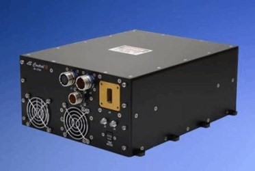
The typical TWTA consists of a traveling wave tube, an RF input section, a power supply & logic interface section, and an RF output section (Fig. 1). For high-power TWTAs in commercial and military applications, operating frequencies range from 300 MHz up to 60 GHz. TWTAs have demonstrated performance at much higher frequencies, as well, up to 650 GHz.
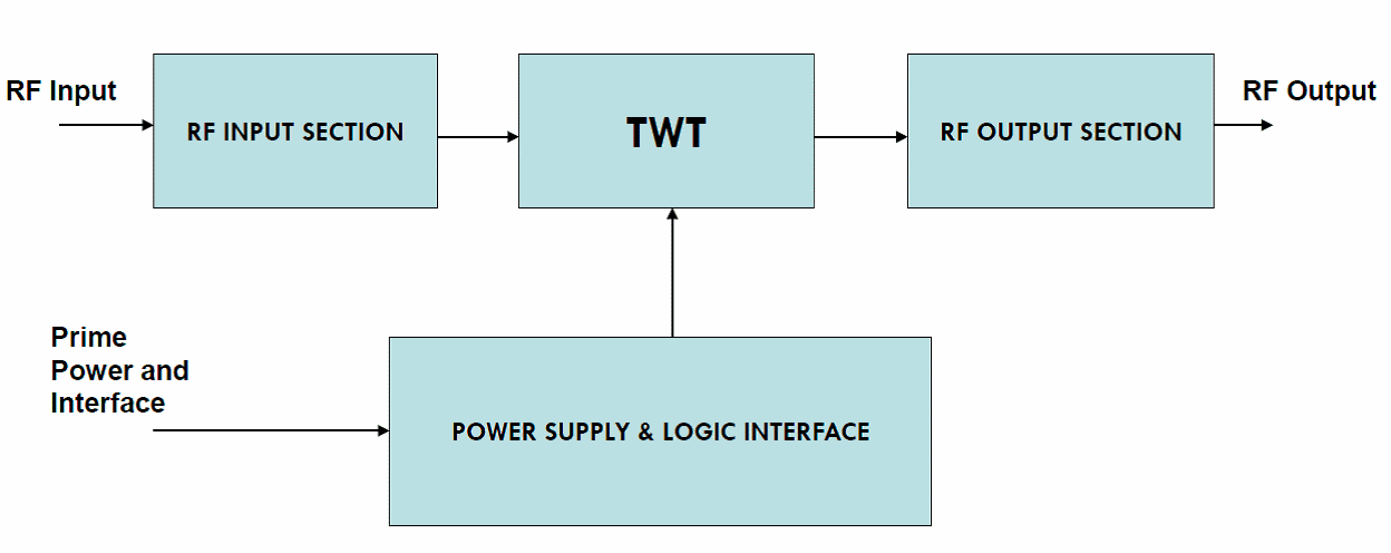
Figure 1 — A Typical TWTA Block Diagram
The TWT, developed in the 1930s, is one of two critical components in a TWTA and the amplifying portion of the high-power amplifier (HPA). The other critical component is the high-voltage power supply, which powers parts of the TWT, enabling amplification of the input signal. The TWT shown in Fig. 2 is a vacuum tube with internal components, in which an input RF signal directed into the input window travels through the TWT structure, resulting in a higher RF signal at the output window.
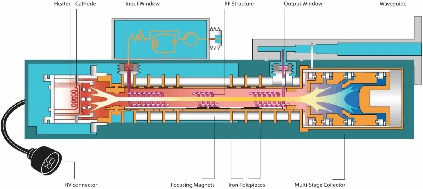
Figure 2 — A Helix TWT
Fig. 2 depicts a Helix TWT. These account for more than half of all microwave vacuum tubes due to their ability to operate over a wide bandwidth, offer low noise and high gain, and cover a wide range of frequencies. The frequency spectrum continues to get more crowded, driven by the insatiable demand for higher bandwidths in commercial applications, and new military threats at higher frequencies are creating requirements for millimeter-wave systems. The requirements that cannot be met with helix TWTs are now finding a home for folded waveguide TWTs and other TWT technologies supporting up to 100 GHz and beyond at output powers unimaginable just within a few year ago.
SSPAs
The solid-state amplifier module, depicted as triangles in Fig. 3, consists of either GaAs (Gallium Arsenide) or GaN (Gallium Nitride) field-effect transistor (FET) devices. The low-power driver and medium-power stages typically are GaAs or GaN, and the higher-power stages are GaN. The SSPA comprises of the amplifying devices, power dividers, and power combiners. The required output power is achieved by adding more combining stages.
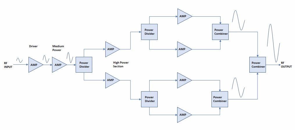
Fig. 3 — A Typical Solid State Amplifier Block Diagram
Fig. 3 depicts a four-stage combiner. Power combiners, especially at higher frequencies, exhibit considerable loss, which can severely degrade the amplifier’s efficiency and resulting in heat that needs to be dissipated. In theory, combining four amplifiers should result in an output power four times the input power, but due to combiner or coupler losses, the typical output in such a setup is only about three times the input power. As you increase the number of combiner stages, losses increase, resulting in lower efficiency. This is one limitation of the SSPA that is not shared by the TWTA. Another SSPA limitation is its inability to operate efficiently at the higher frequencies enabled by TWTA use.
The good news is that as GaN technology advances and matures, higher-power SSPA FETs and modules will become available, and SSPAs will require fewer stages of combining to meet higher power requirements. GaN also has superior thermal handling capabilities compared to GaAs, which helps it better achieve heatsinking sizes on par with comparable TWTAs. Innovative combining techniques, such as spatial power combining technology, can also reduce combining losses. Finally, GaN devices will eventually operate at higher frequencies, though currently they are limited to Ka-Band at low power.
Thus, for low frequencies up to Ku-Band and Ka-Band, GaN SSPAs are a viable alternative to TWTAs for high-power amplification.
TWTAs or SSPAs
Whether the environment is on a satellite in space, a high-altitude fighter Jet, a UAV, or an air-conditioned lab, there is either an SSPA or a TWTA solution. The TWT efficiency used on a satellite approaches the 60% mark. This is achieved by a much more efficient collector design of 4 and sometimes 5-stage collectors. All TWTs or vacuum devices have limitations in bandwidth, power, and operating frequency. As helix TWTs reach their physical limitations at frequencies above 60 GHz, new developments are emerging in millimeter-wave vacuum devices as mentioned earlier. These TWTs are pushing the frequency upper boundaries. Their application is primarily where CW signals require amplification, whether for communications or EW systems. Helix, on the other hand, offers wideband solutions for frequencies below 60 GHz. Some dB Control products offer TWT efficiencies in the mid-40 % range. This is a great option for EW or communication systems operating in harsh environments, at altitude, and with limited prime power as well as cooling restrictions.
SSPAs tend to be much lower in cost than MPM/TWTA designs. One of dB Control’s SSPA products, dB-8015, offers a 150W solution from 2-18GHz. This can help replace 2 TWTAs that operate from 2-6GHz and 6-18Ghz. The argument can be made that, since one SSPA module replaces 2 TWTAs, the prime power requirement suddenly becomes irrelevant but still needs careful consideration and design review. dB Control also offers a 2-6GHz SSPA solution and a 6-18GHz MPM solution that leverages both SSPA and MPM advantages.
The SSPA also takes advantage of a fast ON/OFF ramp rate of under 50nS. This means that if the SSPA is operated in this manner, Prime Power consumption is correlated with the duty cycle during device pulsing. The TWTA or MPM Power supplies have a limit on how quickly the beam can be enabled, especially for TWTs with a Focus Electrode design.
For Radar systems, the TWT offers minimal phase and amplitude stability from pulse to pulse. dB Control’s X-band pulsed products offer low phase noise, low spurious, and pulse-to-pulse stability. This is achieved through dB Control’s low-ripple, minimal-droop, and robust Grid modulator designs.
Early SSPA radar designs used pulsed, combined high-power devices to achieve a high-power pulse. In some cases, this resulted in a power droop across the RF pulse. This is a critical parameter for radar system designs. This has been mitigated by Phased Arrays and AESA radar systems. They are complex systems in which multi transmit (TX) and receive (RX) modules are used. They also offer flexibility and some SSPA advantages, such as soft-fail, instant-on, and others, as noted in Table 1. Some disadvantages include complex system architectures, which can result in high development and recurring costs.
Conclusion
TWTAs sometimes are subject to negative perceptions and opinions because they’re considered “old technology.” Although they’ve been around since the 1930s, TWTAs have benefited from innovations and remain relatively unmatched in power. Additionally, due to their superior efficiency, wide bandwidth, high operating frequency, and high power output, they remain preferred for aerospace applications. In fact, many modern UAVs (such as General Atomics’ MQ-9 Reaper) and manned aircraft use synthetic aperture radar (SAR), EW, and ECM systems powered by TWTAs.
TWTAs are also used for major airborne datalink, RADAR, EW, and ECM applications. That said, there are applications where SSPAs have an advantage, such as some lower-power electronic countermeasures and LEO satcom. Also, maturing GaN SSPA technology and innovative combining techniques will soon complicate the choice between a TWTA and an SSPA, and the decision to use either solution will come down to good old Ben Franklin’s pro/con rules of decision-making.
Looking ahead, dB Control is expanding its SSPA offerings with new rackmount and hubmount amplifier solutions designed to deliver higher power, improved efficiency, and enhanced reliability for demanding RF and microwave applications. Built with the latest solid-state technologies, these new SSPAs offer flexible, high-performance options to meet modern system requirements. To explore dB Control’s latest amplifier and RF product offerings, visit the datasheet library
dB Control has created the comparison guide (Table 1) and the TWTA vs. SSPA Chart (Figure 4) to help you select the amplifier that best fits your application. For more insight, contact the authors at mlee@dbcontrol.com and jgonzales@dbcontrol.com, or visit www.dbcontrol.com
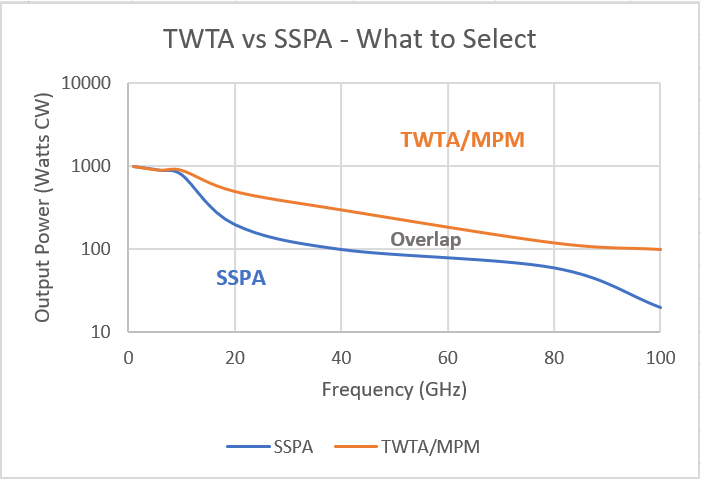
Figure 4 – TWTA vs. SSPA: What to select
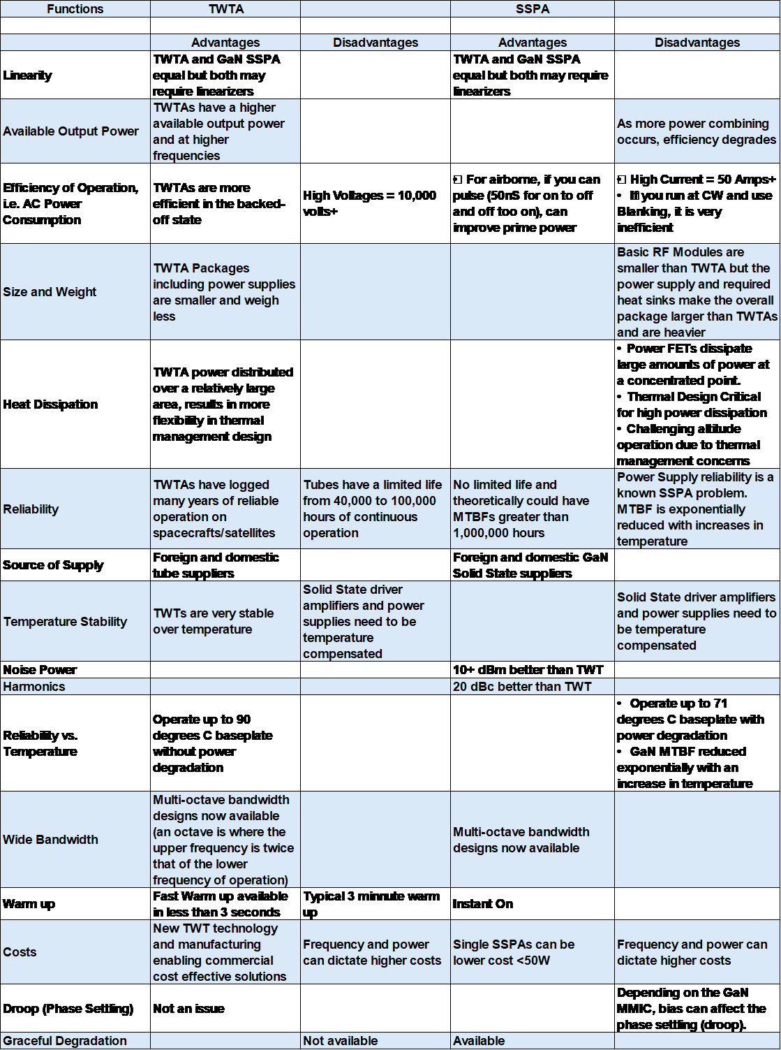
Table 1 – TWTA vs. SSPA: Advantages and Disadvantages
About the Authors